应用提示
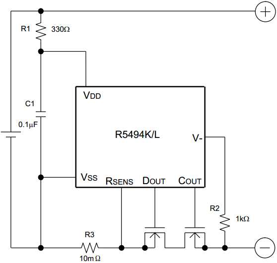
*R1 and C1 stabilize a supply voltage to the R5494K/L. A recommended R1 value is equal or less than 1kΩ. A large
value of R1 makes detection voltage shift higher because of the conduction
current flowed in the R5494K/L.
Further, to stabilize the operation of R5480, use the C1 with the value of
0.01μF or more.
*R1 and R2 can operate as a current limit against setting cell reverse
direction or applying excess charge voltage to the R5494K/L. While small value
of R1 and R2 may cause over power dissipation rating of the R5494K/L, therefore
a total of “R1+R2” should be 1kΩ or more. Besides, if a large value of R2 is
set, release from over-discharge by connecting a charger might not be possible.
Recommended R2 value is equal or less than 10kΩ.
R3 is a resistor for sensing an excess current. If the resistance value is too
large, power loss becomes also large. By the excess current, if the R3 is not
appropriate, the power loss may be beyond the power dissipation of R3. Choose
an appropriate R3 according to the cell specification.
The typical application circuit diagram is just an example. This circuit
performance largely depends on the PCB layout and external components. In the
actual application, fully evaluation is necessary.
Over-voltage and the over current beyond the absolute maximum rating should not
be forced to the protection IC and external components.
Although the short protection circuit is built in the IC, if the positive
terminal and the negative terminal of the battery pack are short, during the
delay time of short limit detector, large current flows through the FET. Select
an appropriate FET with large enough current capacity to prevent the IC from
burning damage.
We are making our continuous effort to improve the quality and reliability of
our products, but semiconductor products are likely to fail with certain
probability. In order to prevent any injury to humans or damages to property
resulting from such failure, users should be careful enough to incorporate safe
measures in design, such as redundancy, fire-containment, and fail-safe
feature. We do not assume any liability or responsibility for any loss or
damage arising from misuse or inappropriate use of the products.
If the positive terminal and the negative terminal of the battery pack are
short, even though the short protection circuit is built in the IC, during the
delay time until detecting the short circuit, a large current may flow through
the FET. Select an FET with large enough current capacity in order to endure the
large current during the delay time.
Sense
resistance and on resistance of the MOSFET selection guideline
Short mode is detected by the current base or the relation between VDD at short
and total on resistance of external MOSFETs for Cout and Dout.
If short must be detected by the current base determined by Vshort and R3, the
next formula must be true, otherwise, the short current limit becomes
(VDD*-0.9)/(R3+Rss(on))
VDD*-0.9 ≥ Vshort
R3
Rss(on) R3
*Vshort =
VDET3× 3 or VDET3× 4
*R3 = External current sense Resistance(Ω)
*Rss(on) = external MOSFETs’ total ON Resistance(Ω)
*VDD* = VDD level at short mode. If VDD goes down by the short current, the
lowest level is VDD*.
Notes: in
case of the short mode is specified at short current determined by the relation
between R3 and Vshort value,
ex. 1
*As the Rsense, in case that the 10mΩ is selected as R3 and if the VDD* becomes
3.0V, to detect short at 9A with Vshort = 0.09V, the Rss(on)
must be 223mΩ or lower.
ex. 2
*As the Rsense, in case the 20mΩ is selected as R3 and if the VDD* becomes
3.0V, to detect short at 8A with Vshort=0.16V, the Rss(on) must be 242mΩ or
lower.
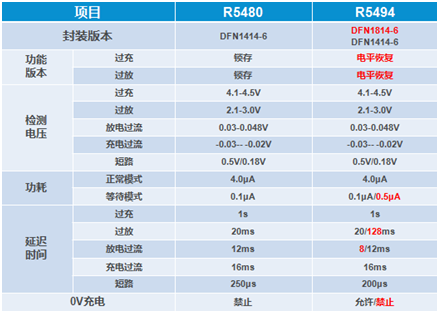
R5494K/L是R5480K的更新版本,在封装、功能和精度上都有变更,区别如下: